Optimising our shadows in Unity

Background

Shadows Still

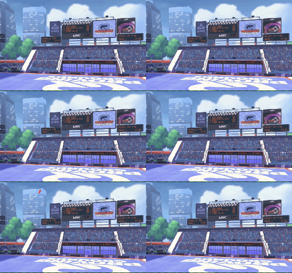
We have a projected shadows system that we use in a few of our games. Very much like a shadow map, it involves rendering objects from the perspective of a light and then projecting the shadows from that light onto the scene.

On some of our games, the fully fledged Unity shadow mapping solution is overkill – we don’t want to render dynamic shadows for everything, only smaller objects in the scene. We also want more control over how we filter our shadows – how we blur them to make them softer.

During a recent profiling session on one of our games, we noticed that generating one of these shadow maps was taking up approximately 12% of the total frame time. So I went about investigating it and looking into what we could do to reduce this cost and at the same time reduce the amount of memory the system was consuming.

Optimisations

My first step was to fire up my preferred profiling tools for both Android (RenderDoc) and iOS (XCode). RenderDoc is a free to use profiler and debugger that can connect to a host Android device and capture frame traces.

RenderDoc

RenderDoc

XCode is to the go-to development app on MacOS, you can capture a GPU frame at any time by selecting the option from the debug menu.

XCode.png

XCode GPU Frame Debugger

Making the most of the space we have

Using the render target viewer on both platforms I spotted that the contents of the shadow map render target was only occupying a small section of the entire texture. I would estimate that over 50% of the pixels in the render target were unoccupied – what a waste of space!

We use our projected shadows with directional lights, orthographic projection modes tend to be easier to control and tweak. You will lose any perspective but for us, this isn’t an issue. Swapping the projection mode over to orthographic as well as better positioning of the light source allowed us to make better use of the available render target space.

In the end, we were able to reduce the resolution of our shadow map texture from 128×128 to 64×64 – that’s 1/4 of the original size. One of the biggest bottlenecks in mobile devices is bandwidth – mobile devices have small busses. Moving 75% less data down the bus is a big saving. This along with shading 75% fewer fragments is a huge win (ignore the colour for the minute – I changed the way we store the shadow map in the render texture).

Shadows-OldProjectionShadows-NewProjection


MSAA

As we are using such a small render target when objects start moving within the render target you will notice a lot of aliasing. Due to the way in which mobile GPUs work, MSAA is very cheap. Mobile GPU’s use a tile-based architecture. All of the anti-aliasing work is done on chip and all additional memory is on tile memory. Enabling 4x MSAA with a smaller render texture gave us much better results with only a tiny increase in processing cost.

Render Target Formats

I spotted that our shadow map render texture was using an R8G8B8A8 format. Only two of the channels were being used. The first (R) was being used to store the shadow itself, and the second channel (G) was being used to store a linear fall off. Our artists requested that the intensity of our shadows fall off with distance.

Looking further into it, we didn’t actually need to store both pieces of information here. We only needed the shadow value or the falloff value depending on what was enabled for this shadow projector. I changed the render target format to a single 8-bit channel format (R8). This cut our texture size down by another 1/4. Again this reduces our bandwidth massively,

Blur Method

After we populate our shadow map render texture we blur it. This reduces any artefacts we see from using smaller textures as well as giving the impression of soft shadows. We were using a 3×3 box blur – that’s 9 texture samples per pixel. What’s more we weren’t taking advantage of bilinear filtering with a half pixel offset. I quickly added the option to only sample the surrounding corner pixels along with a half pixel offset, this reduced our sample count from 9 to 5 (we still sample the centre pixel).

You sample a texel from a texture using a texture coordinate. With point filtering enabled, sampling between two texels will result in only one of the texels being sampled. With bilinear filtering enabled the GPU will actually linearly blend between the two texels and return you the average of the two texels. So if we add an additional half pixel offset, we can essentially sample two pixels for the price of one.

Reducing ALU Instructions

Unity doesn’t support the common border texture wrapping mode. Therefore we had to add a bit of logic to our blur shader that checks to see if the current texel is a border texel, and if so keep it clear. This prevents shadows from smearing across the receiving surface. The shader code was using the step intrinsic to calculate if the current texel was a border texel. The step intrinsic is kind of like an if statement, I managed to rework this bit of code to use floor instead, this alone reduced the ALU count from 13-9. This doesn’t sound like much, but when you are doing this for each pixel in a render texture, it all adds up. This wasn’t the only saving we made here, but its an example of what we did.

When writing your shader, head to the inspector in Unity. From here, with a shader selected, you can select the “Compile and show code” button. This will compile your shader code and open it in a text editor. At the top of you compiled shader code you can see how many ALU and Tex instructions your shader uses.

// Stats: 5 math, 5 textures
Shader Disassembly:
#version 100

#ifdef VERTEX

For even more information you can download and use the Mali Offline Shader Compiler. Simply copy the compiled shader code – the bit in between #if VERTEX or #if FRAGMENT – and save it to a .vert or .frag file. From here you can run it through the compiler and it will show you the shader statistics

malisc --vertex myshader.vert malisc --fragment myshader.frag
Mali Shader Compiler Output

Above you can see that the 5 tap blur shader uses

  • 2 ALU (arithmetic logic unit) instructions
  • 3 Load/Store instructions
  • 5 Texture instructions

OnRenderImage

After the end of the blur pass, I noticed that there was an additional Blit – copying the blurred texture into another render target! I started digging into this and noticed that, even though we specified that our blurred render texture is of R8 format, it was R8G8B8A8! It turns out that this is a bug with Unity. OnRenderImage is passed a 32-bit destination texture, then the value of this is copied out to the final target format. This wasn’t acceptable so I changed our pipeline. We now allocate our render textures manually and perform the blur in OnPostRender.

private void OnPostRender()
{
    if (shadowQuality != ShadowQuality.Hard)
    {
        SetupBlurMaterial();
        blurTex.DiscardContents();
        Graphics.Blit(shadowTex, blurTex, blurMat, 0);
    }
}

Depth Buffer

This one is a bit weird – I’m not sure if I like it or not, I’m pretty sure I don’t. If you’re desperate to save memory you can disable the depth buffer. But this means that you are going to get a tonne more overdraw. However if you know what’s going into the shadow map render target and you know there isn’t a lot of overdraw, then this might be an option for you. The only way you’re going to tell is if you profile it, and before you even do this, make sure you’re really desperate for that additional few kilobytes.

Performance Metrics

Here we can see the cost of rendering a single shadow map (the example above). These readings were taken using XCode GPU Frame Debugger on an iPhone 6s. As you can see, the cost of rendering this shadow map is less than 50% of the original cost.

Cost

Thanks to reducing the size of our render targets, using a smaller texture format, eliminating the unnecessary Blit and (optionally) not using a depth buffer our memory consumption went from 320kb down to 8kb! Using a 16-bit depth buffer doubles that to 16kb. Either way, that’s A LOT of saved bandwidth.

Conclusion

Shadows Gif

In the best case scenario, we were able to reduce our memory consumption (and bandwidth usage) by over 40x. We were also able to reduce the overall cost of our shadow system by just over 50%! To any of the art team that may be reading this – it doesn’t mean we can have twice as many shadows 😀 All in all, I spent about 2-3 days profiling, optimizing and changing things up and it was definitely worth it.

Crowd Rendering on mobile with Unity

Background

One of the artists came to me one day and asked “What’s the best way to render a crowd in our game?”. Being a mobile-first studio, it’s not an easy solution. Back in my console days, we could consider instancing and GPU simulations, but our game needs to support OpenGL ES 2.0 and run on devices with a lot less bandwidth and power. Crowd systems inherently consume a lot of processing power, you’ve got to animate thousands of people and each of those people need to look different.

We took a look at what options were available to use. We could simply render a lot of skinned meshes but this is going to be expensive both on CPU and GPU as we need to skin each mesh and then submit it to the GPU. We could use the sprite system in Unity to render a billboarded crowd, but as the camera angles change the sprites would have to be re-sorted. After a while, we realised we needed to come up with a custom solution.

Technique

2D or 3D?

Our crowds were going to be displayed at quite a distance from the camera, on devices with small screens. Therefore fidelity was not so much of a concern. Rendering thousands of 3D skinned meshes on mobile wasn’t really an option, we chose to stick to 2D crowds.

Placement

We need crowd placement to be quick and easy. We don’t want our art team spending hours painfully placing GameObjects inside scenes to signify where a person should spawn. Ideally, an artist should be able to define a region or area where they want people to spawn and when they hit a button it all comes to life.

Crowd Placement

We gave the artists the ability to spawn crowds inside bounding boxes, around a sphere and at points in a mesh. We found that 95% of the time the art team would choose to spawn crowds using a bounding box.

Randomisation

Crowds Up Close

One of the biggest challenges with crowd rendering is having enough variation within the crowd so that it looks believable. This means people in the crowd will need different animations, coloured clothes, coloured skin, hairstyles etc. And those characters that are duplicated will require offset animations so that they look less like clones. You soon realise that people don’t focus on one person in the crowd, they focus on the crowd as a whole. This means that as long as there are enough variation and movement in there it looks pretty convincing.

We allow the artists to randomise:

  • Sprites
  • Position
  • Rotation
  • Colour
  • Animation offsets
  • Scale
  • Movement

Batching

Our games still target older Android devices that only support OpenGL ES 2.0. In order to reduce CPU overhead from issuing too many draw calls, we knew that we would have to batch as many people in the crowd as possible. For this reason, we made the decision that every person within a crowd region would be batched together into one draw call, but this obviously introduces a problem…

Sorting

As soon as you batch everything together you lose any ability to sort individual people within the crowd. So we had to come up with a flexible sorting solution for the artists. We ended up allowing the art team to sort characters in the group along a specific axis (e.g. along the z-axis) or by distance from an object. The latter proved to be the most used option.

[SerializeField] private Transform SortTransform;

private int SortUsingTransform(Vector3 a, Vector3 b)
{
    Vector3 origin = SortTransform.position;

    float dstToA = Vector3.SqrMagnitude(origin - a);
    float dstToB = Vector3.SqrMagnitude(origin - b);

    return dstToB.CompareTo(dstToA);
}

...

var crowdPositions = new List<Vector3>();
// generate crowd positions
crowdPositions.Sort(SortUsingTransform);

Our crowds were used within a stadium, and our camera is always in the centre of the stadium, looking out towards the crowd. Therefore we are able to sort the members of each crowd group by their distance from the centre of the stadium. Every so often you may spot one character rendering in front of another, but again our crowds are so far from the camera that the chances of you seeing this are very, very slim.

Billboarding

We do all of our billboarding within the vertex shader. We generate 4 vertices for each crowd member, each of the verts is located at the centre of the rectangle. We bake a scale into the vertex data and then this scale is used along with the uv’s to offset the vertex from the centre and align it to the camera.

inline float2 GetCorner(in float3 uvs)
{
    return (uvs.xy * uvs.z);
}

inline float4 Billboard(in float4 vertex, in float3 uvs)
{
    float3 center = vertex.xyz;
    float3 eyeVector = ObjSpaceViewDir(vertex);

    float3 upVector = float3(0, 1, 0);
    float3 sideVector = normalize(cross(eyeVector, upVector));  

    float3 pos = center;
    float3 corner = float3(GetCorner(uvs), 0.0f);

    pos += corner.x * sideVector;
    pos += corner.y * upVector;

    return float4(pos, 1.0f);
}

You can see that the uv’s are a float3, not the usual float2. The first 2 components of the vector are standard uv texture coordinates and the 3rd component is the scale of the billboard.

private readonly Vector2[] uvs = new[]
{
   new Vector2(1.0f, 1.0f),
   new Vector2(0.0f, 1.0f),
   new Vector2(0.0f, 0.0f),
   new Vector2(1.0f, 0.0f),
};

var uv = new List<Vector3>(vertCount);
for (var n = 0; n < numberOfCrowdPositions; ++n)
{
    float scale = Random.Range(minScale, maxScale);
    uv.Add(new Vector3(uvs[0].x, uvs[0].y, scale));
    uv.Add(new Vector3(uvs[1].x, uvs[1].y, scale));
    uv.Add(new Vector3(uvs[2].x, uvs[2].y, scale));
    uv.Add(new Vector3(uvs[3].x, uvs[3].y, scale));
}

Lighting

The artists weren’t happy that the crowd didn’t blend nicely with the rest of the scene, they looked flat and a bit out of place. Therefore we developed a bit of code that would bake data from the light probes in the scene into each vertex in the crowd. All of our crowd’s meshes are generated offline, then loaded at runtime.

private Color ProbeColor(Vector3 localPos, Vector3 worldNormal)
{
   SphericalHarmonicsL2 sh;
   LightProbes.GetInterpolatedProbe(localPos, rend, out sh);

   var directions = new[] { worldNormal.normalized };
   
   Color[] results = new Color[1];
   sh.Evaluate(directions, results);

   return results[0];
}

Conclusion

Crowds

In the end, we ended up creating a crowd system that fit our needs exactly. We had to cut some corners in terms of visuals to meet the demands of our target platforms. But we managed to do so and our solution had virtually no impact on performance.

Motion Blur for mobile devices in Unity

What is Motion Blur?

Wikipedia defines motion blur as:

Motion blur is the apparent streaking of moving objects in a photograph or a sequence of frames, such as a film or animation. It results when the image being recorded changes during the recording of a single exposure, due to rapid movement or long exposure.

When we capture an image with a camera, the shutter opens, the image is captured by the sensor and then the shutter closes again. The longer the shutter is open, the more light the sensor can capture. However, leaving the shutter open for longer also means that the image being captured can change.

800px-Dog_Leaping

Imagine we are trying to capture an image of a car speeding along a race tack. If the shutter stays open for a whole second, the car will have shot past the camera and the entire image will be a blur. Now, if we were to open the shutter for a fraction of that time, say 1/500th of a second, chances are we will be able to capture the image with no blurring at all.

Motion blur is a side effect of leaving the shutter open for a long period of time. In games it can be desirable to simulate this effect. It can add a sense of speed and motion to our scenes. Depending on the genre of the game this can add a whole other level of realism to the game. Genres that may benefit from this effect include racing, first person shooter and third person shooter to name a few.

Pipeline Overview

We wanted to develop a motion blur effect for one of our games, a racing game. There are a number of different implementations currently available.

Frame Blur

The simplest method of simulating motion blur is to take the previous frame’s render target and interpolate between that and the current frame’s render target. When programmable shaders first came about, this is how it was done. It’s really simple and easy to implement and it doesn’t require any changes to the existing render pipeline. However it isn’t very realistic and you don’t have the ability to blur different objects in the scene at different scales.

Position Reconstruction

A step up from frame blurring is position reconstruction. In this method we render the scene as we normally would. Then we sample the depth buffer for each pixel in the render target and reconstruct the screen space position. Using the previous frames transformation matrices we then calculate the previous screen space position of that pixel. We can then calculate the direction and distance, in screen space, and blur that pixel. This method assumes that everything in the scene is static. It expects that the world space position of the pixel in the frame buffer does not change.  Therefore, it is great for simulating motion from the camera, but it’s not ideal if you want to simulate finer grained motion from dynamic objects in your scene.

Velocity Buffer

If you really need to handle dynamic objects, then this is the solution for you. It’s also the most expensive of the three. Here we need to render each object in your scene twice, once to output the normal scene render target and again to create a velocity buffer (usually a R16G16 render target). You could circumvent the second draw call by binding multiple render targets if you wish.

When we create our velocity buffer, we transform each object we render from object space by the current and the previous world-view-projection matrix. Doing this we are able to take into account world space changes aswell. We then calculate the change in screen space and store this vector in the velocity buffer.

Implementation

Requirements

We decided to implement the Position Reconstruction method.

  • Frame blurring wasn’t an option – this method was too old school and didn’t offer enough realism.
  • The camera in our game follows the players vehicle which is constantly moving, so even though we can’t simulate world space transformations we should still get a convincing effect.
  • We didn’t want to incur the additional draw call cost of populating velocity buffer.
  • We didn’t want to incur the additional bandwidth overhead of populating the velocity buffer.
  • We didn’t want to consume the additional memory required to store the velocity buffer.

Code

We start by rendering our scene as we usually would. As a post processing step we then read the depth of each pixel in the scene in our shader:

float depthBufferSample = SAMPLE_DEPTH_TEXTURE(_CameraDepthTexture, uv).r;

Then we will reconstruct the screen space position from the depth:

float4 projPos;
projPos.xy = uv.xy * 2.0 - 1.0;
projPos.z = depthBufferSample;
projPos.w = 1.0f;

In C# we pass a transformation matrix into our shader. This matrix will transform the current screen space position as follows:

  1. Camera Space
  2. World Space
  3. Previous frames Camera Space
  4. Previous frames Screen Space

This is all done in a simple multiplication:

float4 previous = mul(_CurrentToPreviousViewProjectionMatrix, projPos);
previous /= previous.w;

To calculate this transformation matrix we do the following in C#

private Matrix4x4 previousViewProjection;

private void OnRenderImage(RenderTexture src, RenderTexture dest)
{
    var viewProj = cam.projectionMatrix * cam.worldToCameraMatrix;
    var invViewProj = viewProj.inverse;
    var currentToPreviousViewProjectionMatrix = previousViewProjection * invViewProj;

    motionBlurMaterial.SetMatrix("_CurrentToPreviousViewProjectionMatrix", currentToPreviousViewProjectionMatrix);

    ...

    previousViewProjection = viewProj;
}

We can now calculate the direction and distance between the two screen space vectors. We then use the distance as a scale and sample the render target along the direction vector.

float2 blurVec = (previous.xy - projPos.xy) * 0.5f;
float2 v = blurVec / NumberOfSamples;

half4 colour;
for(int i = 0; i < NumberOfSamples; ++i)
{
    float2 uv = input.uv + (v * i);
    colour += tex2D(_MainTex, uv);
}

colour /= NumberOfSamples

Controlling the Motion Blur

Once we got all this on-screen, we quickly decided that there was just too much blurring going on. We want most of the scene to be blurred, but the artists wanted vehicles and drives to be crisp. In order to achieve this, with as little pipeline impact as possible, we decided to use the alpha channel to mask out areas of the scene that we didn’t want to blur. We then multiplied this mask by the blur vector to effectively make the blur vector [0, 0].

half4 colour = tex2D(_MainTex, input.uv);
float mask = colour.a;

for(int i = 1; i < NumberOfSamples; ++i)
{
    float2 uv = input.uv + (v * mask * i);
    colour += tex2D(_MainTex, uv);
}

To add to this we also found that objects in the distance shouldn’t blur as much as those in the foreground. To achieve this we simply scaled the blur vector by the linear eye (view space) depth, calculated from the depth buffer (LinearEyeDepth) is a helper function inside the Unity cginc headers.

float d = LinearEyeDepth(depthBufferSample);
float depthScale = 1 - saturate(d / _DepthScale

Conclusion

Out of the box, Unity will support motion blur by generating a velocity buffer for you, but for our requirements this was overkill. We always need to keep in mind that we are a mobile studio, so we need to take performance into account every step of the way. The method we implemented has its tradeoffs, we had to add distance based scaling to prevent objects in the distance blurring too much. However, it gave us a convincing effect due to the fact that our camera is constantly moving. If you have any questions or feedback, feel free to drop me a message on Twitter or leave a comment below.